The criteria taken into account for optimization are as follows:
- Small antenna size.
- Bandwidth measured at -10dB.
- Resonating frequency at 2.4 GHz.
- Reduced complexity in antenna topology.
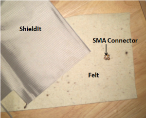
Fig 1 Textile materials and SMA Connector
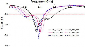
The Figure 3 shows the FS simulated results of the three final prototypes in both high mesh(HM) as well as low mesh (LM) settings. The legend at the right bottom corner shows the S11 of three different prototypes in LM and HM. Prototype 3 yeilds the largest bandwidth of 400 MHz in LM and Prototype 1 with 330 MHz in HM. The difference in their bandwidth is due to increased accuracy in HM setting.
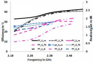
Fig 3 Simulated FS gain and efficiency
The simulated high mesh efficiency and realized gain for free space is provided in Fig 3, showing variation in efficiency and gain with changes in the frequencies within the range of 2.18 GHz to 2.58 GHz. The legend shows the realized gain (G) in decibel, radiation efficiency (re) and total efficiency (TE) in percentage of three different modelled antennas.The efficiency includes total and radiation efficiency. All the three prototypes simulated results are indicated in a graph. The efficiency is within the range of 10 to 40 %, while realized gain is between 0.5 to 2.7dB approximately. The prototype 1 obtains the highest gain of 2.3 dB at 2.4 GHz.
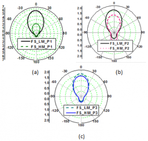
Fig 4 FS radiation pattern in YZ plane for (a) Prototype 1, (b) Prototype 2, (c) Prototype 3
4.2 On-Body
To evaluate the antenna performance in proximity of a human body, a homogeneous body model is used. It is placed under the structure with an air gap of 10mm. It has a relative permittivity of 50.8 and its conductivity is 3 S/m . This air gap emulates a realistic approximation of the actual placement of the antenna on the human body with clothing
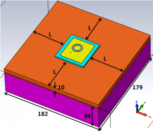
Fig 5 Dimensions of the homogeneous body model (L=62.5mm)
The first prototype has a bandwidth of 297MHz in LM settings and maximum bandwidth of 300MHz in HM setting. The second prototype has a bandwidth of 270MHz in LM settings and 290MHz in HM. Similarly, the third prototype has a bandwidth of 146 MHz in LM and minimum of 151 MHz bandwidth in HM.
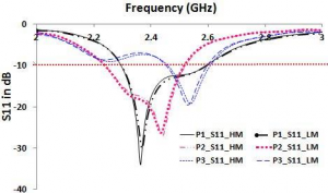
Fig 6 Simulated OB S11 results
The simulated results for all the prototypes are included in a graph with the variation in efficiency and gain with change in frequencies ranging from 2.18 GHz to 2.58 GHz. The maximum gain is obtained by prototype one, which is near to 1.8 dB at 2.58 GHz. The efficiency is obtained within the range of 10 to 40 percentages covering three prototypes’ efficiency in high mesh setting. Individually there efficiencies are deviated from each other by maximum up to 10% and down to 2% at 2.4 GHz. Realized gain is obtained between 0.5 to 1.8 dB approximately.
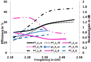
Fig 7 Simulated OB gain and efficiency
The OB performances of the overall antennas brings the variation in the results with distorted radiation patterns. For higest possible degree of accuracy in the results, the modelled is operated in HM apart from LM. The comparison of radiation pattern simulated in OB with low mesh and high mesh setting are shown in Figure 8.
The deviation in magnitude of the main lobe can be observed.
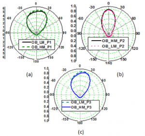
Fig 8 OB radiation pattern in YZ plane for (a)Prototype 1, (b)Prototype 2, (c) Prototype 3
The distortion of the radiation patterns are represented in three dimension where the magnitude of main lobe is deviated by some angle. Moreover, the distortion can easily be observable with asymmetric in the radiation patterns. This is due to the coupling between the human skin and muscles producing the loss in the power.
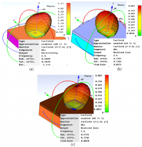
Fig 9 OB 3D radiation pattern
5. FABRICATION
The full ground plane is design and simulation to avoid back radiation and the dimensions of design antennas are taken as small as possible. The patch and ground plane of the antenna are cut using cutters and scissors maintaining the accuracy as far as possible. The substrate is sandwich between two radiators such that there is no air gap between the conducting materials with the help of ironing machine. A snapshot of the fabricated antennas is shown in the Fig 10.
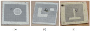
Fig 10 Fabricated antennas (a)Prototype 1, (b) Prototype 2, (c)Prototype 3
6. FIDELITY
The antenna performance evalution is done using CST studio Microwave. This evaluation of the fidelity provides close to the practical information how the designed antenna performs in receiving the field signals in spherical coordinates in various planes.The actual meaning of fidelity (F) is the maximum correlation coefficient of the two signals by varying the time delay (Joardar & A., 2006). The fidelity is computed by determining the absolute max or peak value of the cross-correlation function of the signals (Dumoulin, Ammann, & McEvoy, 2009). This was done using the default Gaussian pulse and the template based post processing in CST MWS.
The FS and OB evaluation is computed by placing probe in spherical coordinate system in theta and phi orientation. Probes were placed at every 45° at 100 cm for FS from the antenna. The position of probes placed by varying either theta or phi and keeping either of them constant.
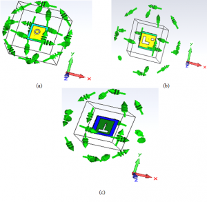
Fig 11 FS probe placement in three different planes for (a) Prototype 1, (b) Prototype 2, (c) Prototype 3
The FS performance evalution of the antennas is done in different orientation placing in various position. The performance results is provided with the two dimensions plot. The maximum fidelity factor obtained are 94.3% at 315o in phi orientation (theta=90, varying phi) by ptototype 1, with 97.5% at 135o in theta orientation (phi=90o, varying theta)by prototype 2 and 97.6% at 90o in Phi orientation (theta=90o, varying phi) for prototype 3.
6.1 On-Body
On body fidelity test probes were placed at every 45° but at 150 cm since the probes are overlapping the design antenna at 100 cm. Fig 13 presents the position of probes placed by varying either theta or phi and keeping either of them constant.Similarly the OB measurements is performed considering antenna as a receiver.The maximum fidelity obtained by prototype 1 is 91.3% at 180o in phi orientation (theta=90o, varying phi, then prototype 2 with 96.7% at 90o in theta orientation (theta=90o, varying phi), and 96.3% at 135o in theta orientation (theta=90o, varying phi) for prototype 3.
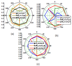
Fig 12 FS simulated fidelity in three different planes for (a) Prototype 1, (b) Prototype 2, (c) Prototype 3.
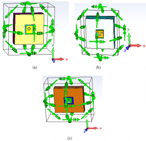
Fig 13 OB probe placement in three different planes for (a) Prototype 1, (b) Prototype 2, (c) Prototype 3
7. CONCLUSION AND FUTURE SCOPE
The initial designs started from a very simple basic structure with the plane patch. Then the slot is introduced to increase the bandwidth. To obtain the required bandwidth below -10 dB, the areas of slot is improved and simultaneously reducing the overall size of antenna. All the proposed antennas operated in 2.4 GHz within the bandwidth ranges of 2 to 3 GHz.
Moreover, the comparison evaluation is also performed between FS and OB environment interms of reflection coefficient, gain efficiencies and radiation pattern.The ATA-FGP of the antenna prove to preserve its S11 performance when it is place on body showing that there is less back radiation in all three antennas.
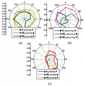
Fig 14 OB simulated fidelity in three different planes for (a) Prototype 1, (b) Prototype 2, (c) Prototype 3
The fidelity factor of each antenna in FS is found to be better than OB.
- To reduce complex design for higer bandwidth, one could double the thickness of substrate. But the designer should not forget with the increase of the substrate height the size and conformity of the antenna reduces.
Complexity during fabrication increases when the design prototypes are small and complex. Here complex in design can refer to the minimum gap used between circular parasitic radiator and main radiator in case of prototype 1. Since the textile has to be cut using manual cutting tools like scissor and knife a gap of 1mm cannot be maintained evenly and also to maintain this gap between circular parasitic radiation and main radiator is a work of the professional.