Kinzang Wangdi1, Thinley Wangmo2, Ugyen Sonam3, Dechen Lhamo4 Kazuhiro Muramatsu5![]()
Electronics and Communication Engineering Department, College of Science and Technology.
* E-mail: ece2011012.cst@rub.edu.bt1, ece2012025.cst@rub.edu.bt2, ece2012028.cst@rub.edu.bt, dechenlhamo.cst@rub.edu.bt3, kazuhiromuramatsu.cst@rub.edu.bt4
ABSTRACT
Snow measurements are required both to study climate and to predict drought, flooding and water availability. Like in the other parts of the Himalayas, Bhutan’s rivers are fed by glacier and snowmelt. Scientific studies carried out in the Bhutan were mostly focused on glaciers, glacial lakes, glacial lake outburst floods and their dynamics because of the fact that the country faces huge threat from these disasters. The Glaciers and their dynamics received much attention, while snow cover and its contribution to runoff has been largely neglected. The effective use of the snow data can result in more efficient decision making that affects many sectors of the economy in a country. Snowfall and snow depth and their water equivalent are some of the most difficult but most important weather elements to measure in an accurate and consistent manner. In this project the techniques to measure snow depth based on the ultrasonic sensor with PIC Microcontroller is being developed. Ultrasonic is the application of ultrasound and a common use of ultrasound is one of the cheapest method for range finding. These devices operate with frequencies from 20 KHz up to several gigahertz. Ultrasonic sensors work on a principle similar to Rader and Sonar which evaluates attributes of a target by interpreting the echoes from ratio or sound waves respectively. Essentially, the use of ultrasonic sensors is the most reliable and inexpensive method for distance measurement.
Key Words : LCD, PIC Microcontroller, Snow Depth, Temperature Sensor, Ultrasonic Sensor.
INTRODUCTION
The data of snow depth is one of the key features for the weather measurements and predictions. Ice and snow on the land surface and sea collectively are known as the cryosphere. It is one of the most important components of the earth’s climate system. Snow has a profound effect on the national economy as well to worldwide. Snow depth is often measured using either ultrasonic or radar sensor. With the aim to reduce complexities and cost a system operating with the cheap and popular HC-SR04 ultrasonic sensor is embedded with PIC microcontroller PIC16F877A and temperature sensor LM35 is proposed. The ultrasonic sensors works by measuring the time required for an ultrasonic pulse to travel to and from a target surface (snow layer). The ultrasonic sensor is generally used for the field of measurements due to their rugged, ease of data interpretations and low cost. Ultrasonic is the application of ultrasound. The term sonic is applied to ultrasound waves of very high amplitudes. The audible frequency range for human are from 20Hz to 20KHz. Ultrasound devices operate with frequencies from 20 KHz up to several gigahertz. Ultrasonic sensors work on a principle similar to Rader and Sonar which evaluates attributes of a target by interpreting the echoes from ratio or sound waves respectively. Ultrasonic sensors generate high frequency sound waves and evaluate the echo which is received back by the sensor.
Background Study
Sound is a mechanical vibration transmitted by an elasthic medium. The range of frequencies that the human can hear is approximately between 20 Hz to 20,000 Hz. The speed of sound travels depends on the medium through which it passes (the square root of the ratio) to the stiffness of the medium and its density and also the environmental conditions basically the temperature (Abdullah, 2015). This application is based upon the reflection of sound waves. Sound waves are defined as longitudinal pressure waves in the medium in which they are travelling. Subjects whose dimensions are larger than the wavelength of the impinging sound waves reflect them and the reflected waves are called echo (Raju, October, 2001). In air, speed of sound is approximately 345 m/s, in water 1500 m/s and in a bar of steel 5000 m/s. In order for the travelled sound signal to be measured, the transmitted signal first needs to be reflected which varies with a number of factors such as the surface of the reflecting medium, size, distance and the angle of inclination of the objects surface facing the ultrasonic sensor (Palma, 02/2008).
Physical Properties of snow and Ice
The reflectivity of sound waves is inversely proportional to the specific density of snow. The characteristics and age of snow can affect how sound waves travel. The fresher snow tends to absorbe more sound waves. According to the study and analysis carried out by Wroclaw University of Technlogy, they found out that the specific density of Ice is much greater than Snow, 900kN/m3 and 1 kN/m3 respectively (T.Gudra, 2011).
Cost Analysis
The one of the constraints of fast growing technology is price. The price play major role in market. The existing device used to measure depth of snow are very expensive. For example, USH-8 ultrasonic sensor cost $149.99, MB7364 HRXL-MaxSonar cost $167.50, SR50A-L ultrasonic ranging sensor cost $223.14 etc.,. Therefore, with the aim to reduce complexities and cost, the simple system were proposed.
ARCHITECTURE
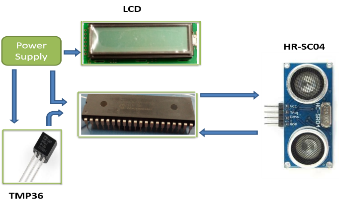
Power supply
Power supply is the most important items of the whole circuit as it need to activates the PIC microcontroller, LCD, ultrasonic sensor and temperature sensor. In the proposed project the power supply from substation voltage which converts high voltage AC to a low voltage DC of 15V is used. Then it is rectified using bridge and regulated to 5V using IC LM7805. While using single +5Vdc, the rectifier heat up very fast due to current drawn by the ultrasonic sensor, LCD and Microcontroller. All of them operate at +5Vdc, the single power supply get heavy loaded so three separate +5Vdc is developed and used.
PIC Microcontroller
The microcontroller used in the proposed system is PIC 16F877A since it does not require large amount of memory as well as a cost effective solution. A ceramic resonator is connected to OSC1 and OSC2 pins (13 and 14) of microcontroller, to provide clock for its operation. The DC supply voltage (VDD) of the microcontroller, pins 32 and 11 are connected to the voltage regulator to deliver constant voltage of +5V and pins 31 and 12 (Vss) of the microcontroller to the ground for necessary operation of the system.
Temperature Sensor
The temperature sensor is interfaced to the microcontroller for measuring temperature of the environment in degree Celsius and thereby computing the speed of the sound wave to obtain a more accurate distance measurement.
Ultrasonic Sensor
The ultrasonic sensor is connected to the microcontroller to compute the distance and display on the LCD. The technique of distance measurement using ultrasonic wave in air include continuous wave and pulse echo (time-of-flight) technique. In this project, the time-of-flight (TOF) method is implemented in which the microcontroller provides a trigger signal to the ultrasonic sensor module. The trigger signal must be 10uS of high time for the ultrasonic signal to propagate toward the intended target with minimum attenuation so that the ultrasonic sensor can effectively receive the echo signal (Rajan P Thomas, Jithin K K, Hareesh K S, Habeeburahman C A,Jithin Abraham, Feburary 2014). When the ultrasonic sensor module receives the trigger pulse, the ultrasonic sensor module automatically generates 40 KHz of sound wave and transmits to the object. Upon having contact with the object this signal gets reflected and is received by the ultrasonic sensor module. The microcontroller calculates the time taken by the ultrasonic signal to reach the object and back to the sensor. The distance can be computed easily by knowing the speed of sound in the medium and time delay of the transmitted and reflected signal.
LCD Display
The LCD (Liquid Crystal Display) provides user interfaces and are very useful for debugging purpose. To interface PIC microcontroller with LCD displaying the texts comes in different sizes and shapes. In this project character which is a very basic LCD module is being deployed. This type of modules can display two lines with 16 characters. The LCD display is a very basic and low cost module. Interface between LCD and PIC microcontroller can be either 4-bit or 8-bit. The difference between 4-bit and 8-bit is in how the data or command are being send to the LCD. Most often, the Read/Write (R/W) pin is just tied to ground and the LCD is only written to and not read.
PROTEUS SIMULATION
The proposed circuit diagram is drawn and simulated in proteus is as shown below.
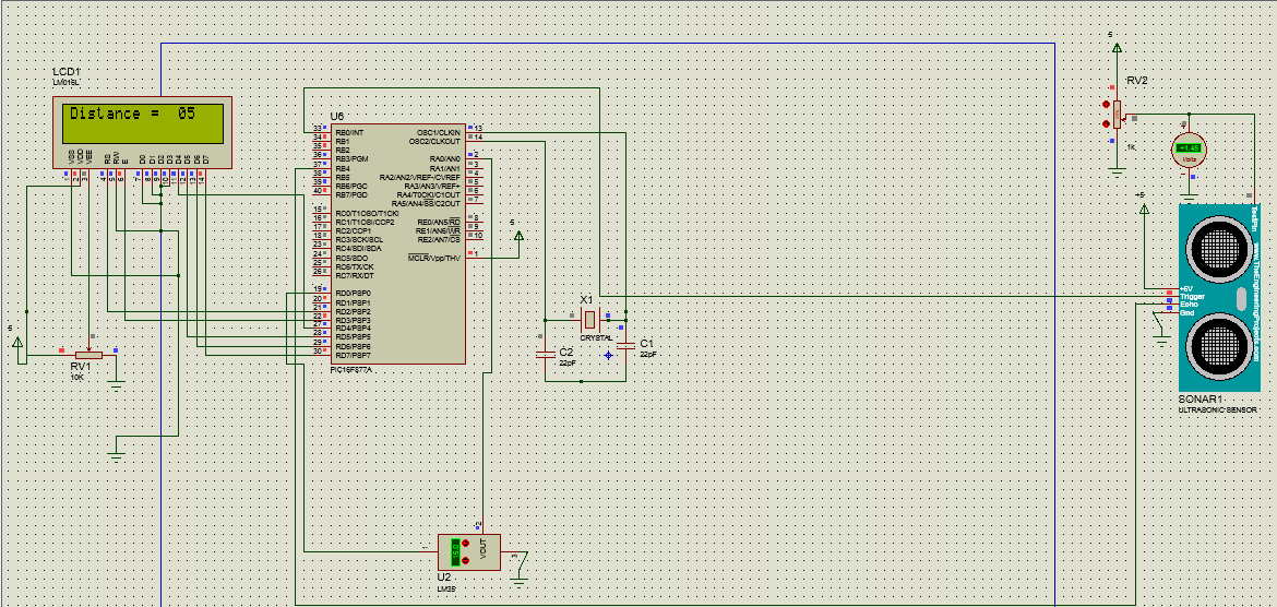
Figure 3: Circuit Schematic of Proposed System
The microcontroller used in the proposed system is PIC 16F877A of 40 pin package. A 10MHz ceramic resonator is connected to internal build oscillator OSC1 and OSC2 pins (13 and 14) of microcontroller, to provide clock for its operation. The DC supply voltage (VDD) of the microcontroller, pins 32 and 11 are connected to the voltage regulator to deliver constant voltage of +5V and pins 31 and 12 (Vss) of the microcontroller to the ground for necessary operation of the system. The temperature sensor TMP36 is interfaced to the microcontroller for measuring temperature of the environment in degree Celsius. The ultrasonic sensor is connected to the microcontroller to compute the distance and display on the LCD. The technique of distance measuluerement using ultrasonic wave in air include continuous wave and pulse echo (time-of-flight) technique. In this project, the time-of-flight (TOF) method is implemented in which the microcontroller provides a trigger signal to the ultrasonic sensor module. The trigger signal must be 10uS of high time for the ultrasonic signal to propagate toward the intended target with minimum attenuation so that the ultrasonic sensor can effectively receive the echo signal (Rajan P Thomas, Jithin K K, Hareesh K S, Habeeburahman C A,Jithin Abraham, Feburary 2014). When the ultrasonic sensor module receives the trigger pulse, the ultrasonic sensor module automatically generates 40 KHz of sound wave and transmits to the object. Upon having contact with the object this signal gets reflected and is received by the ultrasonic sensor module. The microcontroller calculates the time taken by the ultrasonic signal to reach the object and back to the sensor. The distance can be computed easily by knowing the speed of sound in the medium and time delay of the transmitted and reflected signal. The equation for distance measurement is given by:
Where L the distance between the sensor and target surface in meters, c is the ultrasonic speed in the medium measured in meters/second, and t is the flight time of the ultrasonic pulse in second. The speed of the ultrasonic wave depends on the type of the medium and temperature. In air the speed is given by (Abdullah, Design and Implementation of Ultrasonic Based Distance Measurement Embedded System with Temperature compensation, june 2015):
And TC is temperature in degrees centigrade. Finally the distance is computed by the microcontroller and is displayed in the 16X2 LCD.
FABRICATION AND HARDWARE TESTING
Before carrying out the testing of the proposed circuit with ice block, it was tested using different targets such as books, breadboard and wall in laboratory.
While testing, the distance measured by proposed circuit and distance measured manually was same. The maximum distance that ultlrasonic sensor can measure is upto 4meter theoretically but practically it can upto to 3.41 meter only.
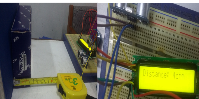
Figure 4 : Testing of circuit with different targets
The final prototype testing was done by using ice cube as shown in figure 3 .
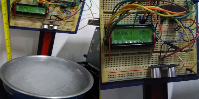
Figure 5: Testing of circuit using Ice block
By measuring three different thickness of ice block the accuracy and precision of the circuit was obtained. The testing was concluded with the device precision percentage of 93.33% and the average accuracy of the device with 92.5%.
FUTURE SCOPE
Following are some of observation drawn from proposed system and value to be add:
-
- Implementing power supply from the solar panel.
- Implementation of remote sensing to transfer data from a remote area to the base station.
- To acquire the baseline data for high altitude risky area.
- To anticipate future sea level rise contributions.
CONCLUSION
Snow measurements are required both to study climate and to predict drought, flooding and water availability. The effective use of the snow data can result in more efficient decision making that affects many sectors of the economy in a country. Snowfall, snow depth and their water equivalent are some of the most difficult but most important weather elements to measure in an accurate and consistent manner. Snow being one of the most important components of the earth’s climate system and profound effect on the national economy, the small circuit using ultrasonic sensor with PIC microcontroller 16F877A was proposed. The proposed project was simulated in Proteus simulator and programing of PIC 16F877A is done using MPLAB.
For any technology the trade off between cost and features are must. Proposed project aim to do cost analysis of existing system and developed cheaper device to measure the depth of snowfall in order to keep a baseline data for future studies on snowfall.
ACKNOWLEDMENT
our hearfelt gratitude goes to our guide Ms.Dechen Lhamo, Associate Lecturer, ECE Department, Dr.Kazuhiro Muramatsu, senior lecturer, ECE Department for timely feedback and unlimited support. We are also very thankful to all Lecturers of ECE department for their feedbacks.
REFERENCES
Abdullah, R. H. (2015). Design and Implementation of Ultrasonic Based Distance Measurement Embedded Systems with Temperature Compensation. india: International Journal of Emerging Science and Engineering (IJESE).
Abdullah, R. H. (June 2015). Design and Implementation of Ultrasonic Based Distance Measurement Embedded System with Temperature compensation. Sulaimani, Kurdistan Region, Iraq: Blue Eyes Intelligence Engineering and Sciences Publication Pvt Ltd.
Palma, L. P. (02/2008). Ultrasonic Distance Measurer Implemented with the MC9RS08KA2. USA: free scale semiconductor.
Rajan P Thomas, Jithin K K, Hareesh K S, Habeeburahman C A,Jithin Abraham. (Feburary 2014). Range Detection based on Ultrasonic Principle. India: International Journal of Advanced Research in Electrical Electronics and Instrumentation Engineering.
Raju, M. (October, 2001). Ultrasonic Distance Measurement with the MSP430. Texas Instrument.
Santos, R. (2013). Complete Guide for Ultrasonic Sensor HC-SR04. Retrieved from Complete Guide for Ultrasonic SensorHC- R04:http://randomnerdtutorials.com/complete-guide-for-ultrasonic-sensor-hc-sr04/
SensComp. (2016). SensComp, Global Components. Retrieved from SensComp, Global Components: http://www.senscomp.com/ultrasonic-sensors/series-7000-sesors.php
T.Gudra, L. (2011). Ultrasonic investigation of Snow and Ice Parameters. Poland: Warcow University of Technology.